In an ion drive, propellant mass is reduced to streams of charged particles and ejected at almost the speed of light. There are many theoretically possible mechanisms for accelerating this stream — electric, magnetic, gravitic and perhaps other mechanisms — with either continuous or pulsed output; with or without rotation. Some methods (as applied by Earth's engineers) appear to have inherent limitations of exit velocity or power. Naturally occurring mechanisms (such as those that produce the relativistic jets from supermassive black holes in the nuclei of active galaxies) may be considerably more effective. The mechanisms applied in the sublight drives of STAR WARS are (at this stage) unknowable in their particular details. However, taking a more positive view, we can observe that these devices do work in STAR WARS, and we can therefore make progress in the more important task of inferring power and effective output from the engines' observed performances.
An efficient ion drive provides maximum thrust whilst conserving propellant. It emits a very small mass efflux at very high velocities. Ideally, the relativistic kinetic energy of the exhaust particle stream should vastly exceed the mass-energy of the particles when they were at rest. Thus the momentum and energy fluxes of the stream are approximately light-like. The efflux is more akin to a cosmic ray shower than to a fountain of exhaust gas.
If F is the total thrust force (in newtons), μp is the drive's efflux of propellant (kg/s) and v is the exit velocity of the ions, then
F = γ μp v
where γ = 1 / ( 1 − v²/c² )1/2 is the exhaust “Lorentz factor” and c = the speed of light. It is possible to achieve almost arbitrarily great thrust with almost arbitrarily low mass flux by making v sufficiently close to c. In the optimal limit of negligible mass efflux, the power (in watts) of the engine system is P = F c. This relation also holds to the thrust obtained by radiation pressure, by the unidirectional emission of massless particles. (However free massless particles tend to be uncharged, which limits the possibilities for manipulating their beams, e.g. with thrust vectrals.)
The energy that runs the engines is supplied by the ship's reactor (which can either be an integral part of the engine or a separate device). The reactor generates power by annihilating some kind of fuel mass (matter, antimatter, “hypermatter”, or a less efficient processes such as nuclear fusion). The resulting power is available to the ship's systems, but most especially the engines. The effective fuel annihilation rate in the reactor (in kg/s) is μf = P/c². If the power couplings are optimal and the engines can draw the reactor's full power, then the peak reactor output is approximately equal to the engine power when thrust is at maximum, F / c.
Thus if we know the ship's maximum thrust then we have a lower limit on its reactor power and fuel consumption rate. Determining the maximum thrust usually requires measuring the ship's maximum acceleration (a) and making an estimate of the total mass of the ship, its fuel and other contents (M). Then the maximum thrust is F = M a.
It is important to distinguish between reactor fuel and drive propellant. For primitive chemical rockets, the fuel and the propellant are the same thing: a controlled chemical explosion in the reactor produces hot gas that expands out through the thruster nozzle. However the propellant emitted from a Palpatine Era ion drive does not necessarily emerge from the reactor. Reactor fuel is something that is annihilated in the main reactor in order to supply power to all the ship's systems, including sublight drives and weapons. Propellant is matter that is accelerated and ejected from the thruster. This could be substantially different from the fuel, stored in completely separate reservoirs. The faster the fuel consumption, the more powerful the vessel. In contrast, as was noted above, a good ion drive design ejects propellant mass sparingly at high velocity. Low-velocity, high-density thrust streams are possible (e.g. chemical rockets) but they quickly exhaust their supply propellant.
The principles are the same for all ion drives in Star Wars.
Sublight thrusters are not limited to a direct, forward thrust. The exhaust streams of charged particles may be deflected to one side or another by the application of electromagnetic fields. Alternatively, the thruster may apply the [unknown to us] types of fields that comprise particle shields. The visible, external devices that project the fields for angling thrust are sometimes called “thrust vectrals” or “thrust vectoring vanes”. They may resemble flaps, rings or rudders at the mouth of the drive. If the drive mechanism involves rotation or imparts spin to the relativistic particles, then this may provide mechanisms for thrust vectoring, as well as affecting the overall stability and collimation of the stream.
The characteristic timescale for fuel consumption by an ion-drive starship, running at acceleration a, is equal to c/a. If the maximum acceleration of a ship is limited to a fixed value (e.g. because of inertial effects) then the time it takes to exhaust its fuel is t = (c/a) ln( 1 + X ). Here the variable X is defined as the initial ratio of fuel mass to ship's structural mass, X = m(fuel)/m(ship). (The function “ln” is the natural logarithm.) For example, a ship accelerating at 3000G will exhaust itself in 19.6 hours if X=1000; in 13.0 hours if X=100; or in 6.8 hours if X=10. This result is independent of the absolute mass of the ship, only the fuel mass ratio is important.
Periods of hot pursuit or intense space battles are limited by the availability of reactor fuel. If the fuel mass is only a few orders of magnitude greater than the structural mass then maximum acceleration may be sustainable for only a few hours. Episodes of maximum reactor output for other functions (e.g. combat at full firepower) are similarly limited in duration. However normal operations require power levels that are orders of magnitude less than the peak. During idle times, coasting, waiting and searching for trouble, a warship may apply accelerations of a few G or less. This will allow timescales of years between refuelling stops. Starfighters may have lower values of the X ratio than warships have; this is one of the reasons why they have short operating times.
We can infer that starfighters probably are not many orders of magnitude denser than everyday matter, because they don't sink into landing grounds made of mundane rock or concrete. In contrast, warships and battle stations must have much higher values of X (implying that fuel mass vastly exceeds structural mass) in order to supply the power levels that are inferred from their various, documented, destructive feats [e.g. Base Delta Zero]. If vessels like the Acclamator troop ships don't sink into the ground, it is because of sophisticated repulsorlift support.
If the ion drive dispenses its propellent mass efficiently, then the density of the thrust stream will be much less than the ambient interplanetary or interstellar gas, and the ejection velocities will far exceed the sound-speed in either medium. At least in terms of external effects, a starship's thrusters are small-scale analogues of stellar and extragalactic jets (relativistic particle beams ejected from near some black holes or other compact objects). These may be 5 or 6 orders of magnitude less dense than their surroundings.
Since drive plasma is less dense than its surroundings, it must lose momentum and energy due to its scattering and entrainment of natural gas particles in the ship's wake. Because the ejection speeds are supersonic, the streams may exhibit shocks at longer than visible distances. Although the trails are invisible to the naked eye in the ship's immediate vicinity, the effects of a sufficiently persistent ion drive may be observable in gamma-rays, X-rays, radio waves or other forms of radiation over long interplanetary distances. For instance, the way the stream carves an underdense cavity may produce the appearance of a plume-shaped hole when the X-rays from the interplanetary medium are observed.
Out to some large distance from the ship, the thrust particle streams are likely to remain thin, straight, well-collimated cylinders. Passing through the stream anywhere in this region must be dangerous. Even a peripheral exposure is likely to feel like an intense, possibly lethal cosmic ray shower. A particle shield may provide some protection against such irradiation, but any object standing directly in the beam will experience the stream's thrust. The victim could be blown away downstream at hundreds or thousands of G.
Heat transfer from the stream may also be lethal. Even if the stream particles are ice-cold in their own reference frame, their relativistic impact into a solid surface must cause tremendous shock-heating, as bulk kinetic energy is converted to thermal energy. The post-shock temperature may be orders of magnitude greater than the temperature of the undisturbed flow or the interior of the engine that emitted the stream. Depending on mass and surface area, the transgressing object may be vapourised before it is accelerated appreciably. It therefore seems likely that all small starships have at least some minimal shields (including TIE fighters), whether or not they're battle-worthy.
At ordinary inter-ship separations, the relatively narrow drive trails pose little physical risk. The chance of crossing the path of a randomly oriented ship (with intense but well collimated drive streams) diminishes like the inverse square of distance. However, flying deliberately at the tail of a dogfight foe is more hazardous. The survivability of the encounter depends on a comparison between one ship's engine power and the dissipative power of the intercepting ship's shields. Naval ships of comparable power may be able to endure each others' emissions, if their shields are fully raised or if the engines are idling. However the thrust stream of a large commercial or naval vessel may be lethal to a starfighter: a fighter entering a star destroyer's trail within viewing distance of the ship might be torn apart and lethally irradiated instantaneously.
Aside from direct immersion damage, it is unclear whether ion drive trails can inconvenience nearby ships. The streams are invisibly tenuous at optical wavelengths, and therefore a drive trail is unlikely to affect optical sensors. Gunnery tracking systems are probably unaffected. We don't understand the physics of supralight signals in enough detail to say whether drive streams can interfere with them [as asteroid fields do, TESB].
The massless beams of turbolasers, laser cannons, blasters and allied technologies are barely affected by dense air, so they seem much less likely to be affected by drive streams. It is possible that drive streams may interrupt the propagation of shots from an ion cannon, since this plasma of charged particles is qualitatively similar to an ion drive's exhaust. Indeed an ion drive thruster could be regarded as a low-density, high-powered, continually active ion cannon. (An ion cannon is only built to eject plasma in abrupt spasms; and their recoil would only be useful for improvised thrust in a dire emergency.)
“For every action there is an equal and opposite reaction.” An ion drive applies a force where it is mounted on the starship, equal in strength and opposite the direction of the exiting particle stream. Call this the “thrust force” of the engine. These forces cause the vessel to accelerate or turn. The thrust of an engine may vary up to some maximum that depends on the design limitations of the drive components and the maximum power of the ship's main reactor. The streams may be pointed in different directions using electromagnetic vectrals around the nozzle (e.g. Y-wing fighters, star destroyers) or by rotating the nozzle itself (e.g. the engine balls of Geonosian starfighters). Thrust vectoring may be limited by the capabilities of the componentry, or by obstructive by parts of the ship. Pointing an ion stream into the ship's wings or tail is obviously self-destructive, and the drives must include preventative mechanisms. Thus each ion drive is an independent unit that applies a variable force in a variable direction, and we can study the dynamics of the ship by measuring the arrangement of the nozzles.
If an engine's thrust is not directed at the centre of mass then it exerts a torque on the ship. In vector terms, the torque is a cross-product of the force and the separation between its point of action and the centre of mass: τ = r × F. If the torque contributions from the individual thrusters sum to a zero overall torque then the ship simply accelerates in some direction [see “transverse acceleration” below]. If the total torque is non-zero then the ship gains spin whilst accelerating [see “turning” below].
Here we consider the limitations of side-slip manoeuvers, i.e. diagonal combinations of forward and sideways accelerations in the horizontal plane, while the total torque is kept to zero (no spin). The zero-torque condition requires the output and directions of the engines to be balanced in a specific way that depends on the positions of the engines.
When the thrust from all engines is directly aft, the total forwards acceleration is maximum. Diagonal (part sideways, part forwards) acceleration requires different thrusters to work with different intensities, firing in different directions. Accelerations in directions other than forwards require off-axis combinations of thrust, with the engines are partially working against each other, resulting in less than maximum acceleration. Some transverse accelerations are unattainable because of constraints on the individual thrusters' deflection angles. Therefore each starship has a maximum possible transverse acceleration and a maximum heading angle for side-slip manoeuvring.
In order to calculate these preformance limitations, we must identify the centre of mass (not always easy) and measure the relative positions of the thrusters. Measure the thruster's internal opening angle. Disallow the engines from firing into any part of the hull. This limits the angular range of thrust deflection. Require that there is no overall torque (to prevent the development of uncontrollable spin). This yields a set of formulae prescribing the allowable combinations of thruster directions and fluxes.
Designate the maximum output of each engine as the provisional unit "1", so that the maximum straight-line thrust of a twin-engine ship is "2" and that of a triple-engine ship is "3", and so on. In general the maximum straight-line acceleration must be measured or inferred from a ship's performance in the movies, e.g. a star destroyer outrunning the Millennium Falcon, or the rebel fighters rounding Yavin in a few minutes in ANH. Then, for example, if we know that a star destroyer with three primary engines achieves 3000G maximum straight-line acceleration in the movies and if the geometric/dynamic calculations indicate a maximum of "2.5" units of thrust in a particular off-centre direction then the corresponding maximum acceleration is 2500G in that direction.
The shape and distribution of engines is easy to measure from reference images. The accuracy of our estimates of the dynamical limits of a starship largely depends on how well we can estimate the position of the ship's centre of mass (“barycentre”). Normally or ideally, the barycentre should be in the ship's midplane, and equally positioned between port and starboard sides. However a few peculiar ships must have their barycentre far from the mid-plane, e.g. the cigar-shaped Naboo yacht [in AOTC] with its thrusters oddly positioned near the bottom. The centre of mass should be somewhere above the common centre of the landing pads (on a ship that has landing pads) ensuring that the landed ship distributes its weight evenly. The study of starship footprints might help us to identify the barycentres of ships like the Millennium Falcon, rebel transports, Acclamator transport ships, and vessels with even more complicated shapes.
The calculations are fairly simple for twin-engine vessels, since we need only consider two thruster angles and another variable for the power ratio of the engines. Engine measurements can be taken for several classes of TIE fighter craft and a few other twin-engine designs like the Δ-7 Aethersprite fighters flown by Jedi. For the simplest TIEs, we can assume that the centre of mass is at the geometric centre of the cockpit bulb.
Formulation:
If r = distance between each engine and the centre of mass, ε = angular offset between engine and the longitudinal axis through the centre of mass, θ1 and θ2 are the outward/inward deflection angles of the engines, F1 and F2 are their respective thrusts, then the total thrust in the forward direction is Fx, the total thrust in the transverse direction is Fy and the total torque is τ. These values are related as follows:
Fx = F1 cos θ1 + F2 cos θ2
Fy = F1 sin θ1 − F2 sin θ2
τ / r = (F1 sin θ1 − F2 sin θ2 ) cos ε +( F2 cos θ2 − F1 cos θ1 ) sin ε.
If the total torque is zero, τ = 0, then it can be shown that the two engines' thrust and deflection values must be related via:
F1 sin(θ2−ε) = F2 sin(θ1−ε).
For any choice of deflection angles θ1 and θ2 within the physical limits (tabulated above) we can derive the ratio of the engines' thrusts, F1/F2 required to maintain zero torque. Hence the components of the total thurst can be calculated, Fx and Fy. The direction of the acceleration, expressed as an angle off the forward direction, is given by the tangent, tan φ = Fy/Fx.
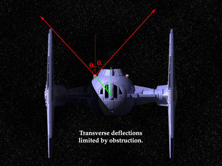
Schematic representation of the limits on thruster deflection, with the example of a TIE fighter (viewed from above). The θ angular limits on thruster deflection (marked in red) are due to obstructions on the ship. The angle between the main axis (blue), the centre of mass and the engine position is denoted by ε (in green).
Results:
Here are some graphical summaries of the transverse manoeuvring characteristics of several starships that are effectively twin-engine craft.
In each file there are five plots.
One interesting fact of TIE fighter geometry is that a single engine firing directly away from the barycentre safely misses the trailing edge of the neighbouring wing. A TIE with one failed engine could point the remaining engine at about 40° and propel itself without spinning. Such a half-crippled TIE could fly with the cockpit facing approximately 40° to the direction of travel. That is more versatile than some designs, like a Y-wing, which would be geometrically incapable of directing the thrust of a single engine opposite the centre of mass. A half-crippled Y-wing would have to perform a cycle of active manoeuvers, alternately building up and working against spin.
The TIE fighter and interceptor have similar characteristics because their engines are arranged identically. The interceptor thrusters can angle up to a wider outer limit because its wings don't extend so far behind the ship (in the mid-plane). However the interceptor's steering ability in zero-torque manoeuvres is limited by the same obstruction posed by the rear hatch. Other designs with rear wing incisions, such as the TIE Avenger [from computer games], may have wider angular limits.
Compared to the TIEs, the Δ-7 Aethersprite is terrible at zero-torque side-slip manoeuvres. One reason is the fin extending between the thrusters: it blocks many potentially useful thrust directions. Another reason is the closeness of the engines to the longitudinal axis (the angle ε is not very large). Of course the Aethersprite can still turn, but that is the subject of another section.
| vessel | θ− | θ+ | ε |
|---|---|---|---|
| TIE Fighter | -45° | 47.3° | 39.5° |
| TIE Interceptor | -45° | 73.5° | 39.5° |
| Δ-7 Aethersprite | -19.5° | 31.2° | 10.9° |
|
The line between the engine nozzle and the centre of mass
subtends an angle ε to the longitudinal axis.
In other words, an individual engine needs to fire at a deflection ε
in order to exert no torque.
The shape of the ship imposes inner and outer limits on engine deflection angles,
labelled
θ−
and
θ+.
| |||
Each extra engine adds more thrust and deflection variables, while the zero-torque condition still only provides one constraint. This provides more flexibility for the helmsman, but complicates our task of calculating to total vector thrust limits.
Let us consider the example of a common mile-long star destroyer. This ship has three equal primary engines, and four minor engines that we shall ignore. The main engines can fire independently, as shown when the thrusters of the destroyer Tyrant blinked separately when the ship was shot by a rebel ion cannon on Hoth [TESB].
The centre of the reactor bulb is the most likely centre of mass, since this is where fuel is drawn for annihilation, and fuel far outweighs the destroyer's normal, solid, structural mass. This point is in the mid-plane, approximately 1170m behind the prow. It is close to the volumetric centre of the hull wedge.
If the thruster bells are roughly 64m deep then an exhaust stream could possibly deflect 20m transversely before hitting the nozzle lip. [Approximate measurements taken and scaled from Imperial star destroyer model kit.] This implies a thrust deflection limit of β≈17.4° off axis in any direction. Transversely, the thruster bells are separated by about 190m. Longitudinally, they are about 1508m behind the bow. This is about 338m behind the assumed barycentre. Therefore, as seen from the barycentre, the outer engines are positioned at an angle &epsilon≈29.3° off the longitudinal axis.
Denote the deflection angles of the left, centre and right engines as θL, θc and θR. Denote the thrust from the individual thrusters as FL, Fc and FR respectively. Choose units such that each of these values is between 0 (inactive) and 1 (full thrust). If the transverse and longitudinal displacements of the engine are y=190m and x=338m, then the torque equation is
τ = y(FR cos θR −FL cos θL) − x( FR sin θR +Fc sin θc +FL sin θL).
If we require zero torque (no spinning or turning) then this equation can be used to prescribe the deflection angle of the central engine, &thetac, provided that we know the other F and θ settings.
Taken together, the zero-torque condition and the deflection and thrust constraints of individual engines limit the attainable (vector sum) thrust in longitudinal and transverse directions. These engine configurations are mapped in the diagram below. It is assumed that at least one of the engines is at maximum thrust. If the destroyer's maximum straight-line acceleration is 3.0 units, then its maximum sideways acceleration is about 0.55. This transverse acceleration is only achievable while there is a forward acceleration of about 1.7.
To achieve a more rapid transverse acceleration, the ship must turn, which means deviating from the zero-torque solutions. Unfortunately we'll need to know much more detail about the internal mass distribution before we can calculate the moment of inertia, which is needed to determine how quickly thruster torque turns the ship.
Thrust diagram of a common star destroyer. The shaded regions show forward and transverse thrust vectors achievable under conditions of zero torque (i.e. the ship doesn't start turning or spinning). The maximum forward acceleration is scaled to 3 units. In absolute terms, this is about 3000G acceleration. In each configuration in this illustration, at least one of the three engines is at maximum. It was also assumed that the idlest engine exerts at least 1/10000 of its potential full thrust.
For each additional thruster that a vessel possesses, there are additional degrees of freedom: two angles of the thrust direction, and the intensity. The solutions for balanced, torque-free manoeuvers are too numerous to quantify here. The nonzero-torque solutions for achieving a chosen rate of spin are similarly numerous.
Starship control systems must be programmed or adapted to each ship's particular engine system. A starpilot would not control the nozzle output and directions directly. His joysticks would allow him to choose or adjust his fighter's total thrust and torque, with the computer then aligning the engines appropriately.
Likewise, the helmsmen of a great starship like the Executor (with 13 engines) could choose the ship's intended acceleration and torque, within the geometric and power constraints, and then let the control systems automatically choose a corresponding thruster configuration. In Executor's case, it is not immediately apparent whether the most important constraints are due to internal deflection limits of the engines or obstruction by hull features such as the fantail. (The fantail may limit the possibilities for “downwards” transverse accelerations more than “upwards” accelerations.) It is a very complicated geometric problem, which we are only likely to solve after obtaining an accurate 3D model of the ship.
For starships with innumerable small engines, we must rely upon some special symmetry of the design in order to infer anything about the thrust and torque limits. Spherical or circular distributions of engines are a soluble class of problems. For an example of a vessel with numerous engines in a ring array, see the commentary about the Death Stars. It is possible to relate the observed maximum torque and maximum linear acceleration of a Death Star. Information about one of these attributes implies constraints upon the other.
Compared to the torque-free manoeuvres, turning solutions are more complicated to calculate. The process of turning a starship [in STAR WARS] could be idealised as four stages.
Ideally, this sequence is performed at a rate that turns the ship to the pilot's desired heading. The apparent complexity of these manoevres is (presumably) hardwired into simplified helm or cockpit controls.
Thruster torques are easy to calculate, if the position of the centre of mass is known. Calculating the moment of inertia — and hence how fast the ship experiences angular acceleration in response to torque — is tricky without knowing the internal mass distribution in detail.
The best hope of making progress would be to infer the moments of inertia from observations of the actual turning abilities of starships. The most useful examples are instances of (presumed) maximum turning, e.g. when fighters are desperately evading enemy fire in open space. In ROTJ, when the rebels guessed that the Endorian shield was still up, the Home One and other ponderous ships turned to avoid collision (taking perhaps a few tens of seconds to turn 180°).
What happens if the starship's thrusters or controls are damaged in such a way that there is a persistent, unbalanced thrust resulting in persistent torque? The vessel's spin will accelerate in one preferred direction. If the rotation is sufficiently rapid, the thrusters apply acceleration approximately equally in all directions perpendicular to the spin axis. If so then there cannot be any overall, residual acceleration. The ship will hurtle off at some approximately constant velocity, in an unpredictable direction. This is apparently what happened to Lord Vader when he was knocked out of the Battle of Yavin. He was lucky (at 50% level) that his random course took him away from the Death Star and not into collision with its surface.
At some stage, an uncontrolled ship's rotation will increase to a point where the tolerances of the inertial compensators are overcome. Then the ship will be torn apart by centrifugal force.
In practice, both the spin and the trajectory may be violently randomised, if the uncontrolled motions affect the operation of the thrusters, or if the angle and power of the thrusters varies. If the thruster deflection angle varies randomly then the ship may take longer to spin up to the breakup threshold on any particular axis.
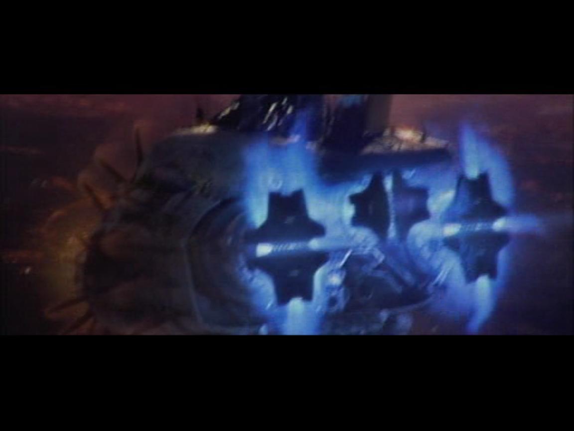
In the Battle of Coruscant [ROTS], General Grievous' flagship Invisible Hand deploys several special breaking mechanisms in attempts to stay in orbit and control its atmospheric descent. During the first loss of control, the captain ordered the use of emergency braking thrusters. These were forward-facing rings that opened around the lips of the main thruster nozzles. These rings emitted thrust plasma forwards, but presumably angled far enough off-axis to avoid hitting the main hull. The endurance of these devices appeared to be limited to a few seconds.
In the second and final loss of control, Anakin Skywalker employed solid vectrals that closed like pairs of shutters over the ion drive nozzles. These devices must have been magnetised or shielded to avoid penetration and erosion by the exhaust streams. The ion efflux was in fact reflected forwards off the shutters: effectively thrust-vectoring by over 90°. As in the first incident, the streams cannot have bent all the way forwards, otherwise the stern hull might have been blown off. The durability of these braking vectrals was not fully tested, since the damaged tail half of the ship broke off under aerodynamic drag. (Hull panels and hatches were open to the atmosphere in the hope of drag-decelerating the whole derelict ship.)
The main thrusters of a starship are usually at the stern and face backwards, parallel to the ship's longitudinal axis. This suits the normal mode of sublight flight. in which the ship accelerates in the direction of its bow. Changes of direction are accompanied and/or achieved by a change of facing and thrust in approximately the longitudinal direction.
Many starship designs also include smaller, inconspicuous thrusters at the front or on the sides, intended to provide brief bursts of thrust in forward or lateral directions. This may be of use for sudden, brief braking actions, or fine adjustment of attitude. For example, the Invisible Hand [Revenge of the Sith novel] is supposed to have retro-thrusters somewhere on its front surfaces. The rebel X-wing fighter is supposed to have tiny retrothrusters on the conical devices leading their wings.
Although they occur in many starship designs, the generally small size of secondary- or retro-thrusters implies that they suffer at least one of three limitations:
If a star destroyer needs to decelerate rapidly (comparable to its forward accelerative ability), then the captain should order a 180° turn so that the main engines face forwards and can apply their thrust directly. Retro-thrusters could not achieve or sustain thousand-G accelerations for long. However the turning manoeuver requires either the application of off-centre attitude thrusters (supplmental thrusters that push at the corners of the hull) or thrust-vectoring (electromagnetically angling the exhaust of the main drives a few angles off-axis). Whether the main drives' electromagnetic baffles are strong enough to bend their ion streams 180° backwards and over the hull (to achieve direct braking) is not yet known.
As an alternative to the use of weak retro-thrusters, a powerful warship could simply fire its main guns forward at maximum intensity, and the recoil would cause deceleration comparable to the main sublight drives. The bursts of plasma fire of a powerful ion cannon is broadly similar to the invisible but continuous ejecta of an ion-drive thruster. Turbolasers experience recoil too, but carry less momentum because of the massless nature of their beams.
When a starship accelerates, the thrust forces are applied at the engines. If the ship and its contents are to follow the engines, and avoid being torn asunder, then the acceleration must be transmitted throughout the structure, either by its material properties or by intangible “tensor fields” that the ship generates actively [TPM:ICS]. (These are analogous to the “structural integrity fields” postulated in other science-fiction tales.) Tensor fields relieve stress, transmit force faster than solid contact and thereby maintain cohesion.
The technology of inertial compensators is related to that of tensor fields. These interior devices apply forces akin to artificial gravity within the ship. The purpose is to protect the crew, contents and ship structure from the inertial forces due to sublight acceleration. The force field of the inertial compensator is actively varied so that it always counterbalances (and cancels) the acceleration forces with the right magnitude and direction. Space flights at multiple thousands of G become survivable because of these devices. Without inertial compensators, the ship's occupants and many of its delicate components would be reduced to paste. To determine a vessel's sublight mobility, the performance limitations of inertial compensators may be just as important as fuel/power limits of reactors or thrust limits of thruster nozzles.
In order to cancel the inertial forces safely, the controlling mechanism needs to anticipate the direction and magnitude of the ship's acceleration. It also needs to respond nearly instantaneously when external forces are applied (e.g. the blow from a nearby explosion). The former might be achieved by linking the inertial compensators with the control systems of the sublight drives. A command to the ion drives may carry a corresponding instruction to the inertial compensators. Internal sensor feedback from the ion drives may inform the compensators to make adjustments.
However the task of anticipating and actively damping external accelerations is more problematic. There must be a lag time in the response, due to the finite duration of processing and the transmission of control signals to inertial compensators across the ship. Intra-ship signals may be limited to light-speed; in that case the typical lag time is determined by the linear size of the ship.
It seems likely that longer lag times will lead to a larger residual of uncompensated inertial forces. This may limit how rapidly a large starship can change the direction or output of its sublight engines (though not the engine output in peak terms). Fortunately, although we may expect larger ships to be more vulnerable to residual forces due to compensator time-lags, big ships generally benefit from greater mass and more effective shield protection. The abovementioned tensor fields may help too.
It must be emphasised that inertial compensators are not a form of propulsion in themselves (even though they are linked to the sublight drives to ensure flight safety). Inertial compensators cannot apply external thrust. They only govern the internal coherence of a vessel. Inertial compensators apply forces between bodies within the ship. They ensure that all parts of the ship accelerate together, as a coherent whole following the engines. They do not negate or diminish a ship's total inertial mass. They do not enable a ship to shed or gain momentum from nowhere. They do not enable a ship to accelerate or change direction. Inertial compensators conserve the ship's total mass, momentum, angular momentum and energy. It is not possible to simply push or pull upon empty space.
A tractor beam projector is a gravitic device that emits a narrow, intangible beam into space. The beam exerts a strong attractive force between the projector and any object in the beam's direct path. The beam and the target are drawn towards their common centre of mass (unless one of the objects is bound to something else). The smaller mass accelerates more rapidly than the larger one. The least massive of these objects accelerates most rapidly. If the tractor beam exerts a force F then the smaller object (of mass m) accelerates at a rate a = F / m. The larger object (of mass M) accelerates in the opposite direction, with a lesser acceleration, A = −F / M. For example, when the Millennium Falcon was ensnared by the Death Star, the battle station was not measurably affected.
The presently available evidence does not reveal an exactly how the tractor force depends on the characteristics of the target. The beam may act like natural gravitation, imposing equal acceleration regardless of the object's mass. Alternatively, the tractor force may depend on the crossectional area of the object intersected by the beam: in which case objects of different densities and sizes would accelerate at different rates. In a more extreme possibility, the tractor force might be the same for any single object in the beam, in which case tiny bodies like interplanetary gas molecules could suffer immensely greater accelerations than a captured starship.
Whatever the detailed physical effects of a tractor beam may be, exerting a tractor beam incurs penalties of structural stress. Like the engine and shield systems, the projector must be securely mounted in the ship's framework, either by physical bracing or immaterial tensor fields [see the Trade Federation landing ship in TPM:ICS]. Otherwise it could be torn free by the reaction forces that oppose the traction applied against the target. Thus the strongest tractor beams will require bulky, heavily reinforced projectors, and could only be installed in larger starships.
Tractor beams have sometimes been employed as an improvised propulsion system. This is possible if the projecting vessel flies amidst more massive targets: deliberately using tractor beams to yank on nearby objects or terrain can affect steering. Tractors or repulsors might also be improvised as a braking mechanism, but only if there is a suitable massive body to act against. Nonetheless, it must be rare to find tractor beams that could persistently compete with the power and strength of conventional sublight drives. (Otherwise tractor beams would have become the primary means of propulsion millennia ago.)
Geonosian starships [AOTC:ICS] are peculiarly furnished with numerous tractor/repulsor projectors which could be used to manoeuvre by grappling massive terrain features or free objects nearby. They can also be used as shearing weapons, attempting to physically rend an enemy ship apart. However these abilities are limited by the fact that projector array experiences reaction forces equivalent and opposite to the forces inflicted on the target.
For the most powerful ships in the galaxy, gunnery recoil effects may be considerable compared to the thrust capabilities of their engines. For the sake of brevity, let us define a “warship” as any combat vessel that can direct a major share of its main reactor output to either its weapons or its engines, and can change that distribution at the captain's orders. The Galactic Empire, the Confederacy of Independent Systems and the Mon Calamari of the Rebel Alliance were great historical powers that owned and deployed warships. Now let us consider how gunnery and propulsion functions may constrain each other.
If a gun emplacement is continually emitting turbolaser fire at a power P then the corresponding recoil thrust is F = P/c. (This is additional to the recoil that may accompany the ejection of spent tibanna coolant or other waste gases.) If the ship is firing in all directions then the overall thrust and torque may be negligible. If however the barrage focuses in a particular arc then the ship will experience an overall thrust in the opposite direction. In the most furious possible space battles, the share of the reactor power directed to guns may be significant compared to the share directed into the engines, resulting in recoil drift.
A star destroyer using maximum firepower could propel itself sideways with an acceleration up to a few thousand of G. The captain must either accept this recoil drift or devote the engines enough power for counter-thrust to maintain position. For the counter-thrust to be effective, it must be equal and opposite the guns' recoil vector. This operation may be equivalent to a transverse manoeuvre of the kind discussed above. The simplest configuration is when all guns fire straight ahead, while the engines fire directly behind. Symmetric fire patterns may be designed to cancel the recoil forces: for instance a destroyer might fly between two targets while the starboard guns fire right and the portside guns fire left.
Heavy weapons recoil is a compelling reason for installing heavy turbolasers in concentrations near the ship's centre of mass (like the main turrets beside the terraces at the back of a star destroyer) or evenly distributed everywhere (perhaps like the batteries on Mon Calamari cruisers). Full-powered shots from the immense bow turbolasers of Separatist Munificent- and Recusant-class star frigates and destroyers could spin the ships dangerously if they're directed off-axis. Dynamically, the worst possible arrangement of guns would be at a ship's extremities, far from the centre of mass. A warship designed with widely spread engines (relative to the barycentre) is better able to maintain position whilst directing maximum firepower far off to one side.
Thanks are due to, in alphabetic order: